© 2014 Foundation Supportworks
        
        
          ®
        
        
          ,
        
        
          Inc.
        
        
          All Rights Reserved
        
        
          p 126


            APPENDIX 2D


          PILE BUCKING CONSIDERATIONS


            Chapter 2


          Helical Foundation Systems


            Davisson Method


          The Davisson Method (1963) considers lateral
        
        
          support from the surrounding soil and variable
        
        
          boundary conditions for the pile. This method is
        
        
          based on manipulation of the governing
        
        
          differential equation which assumes the
        
        
          subgrade modulus of the soil is constant with
        
        
          depth along the pile:
        
        
          Where,


            EI


          = Flexural Stiffness of the Pile


            P


          = Axial Load


            k


          = Subgrade Modulus
        
        
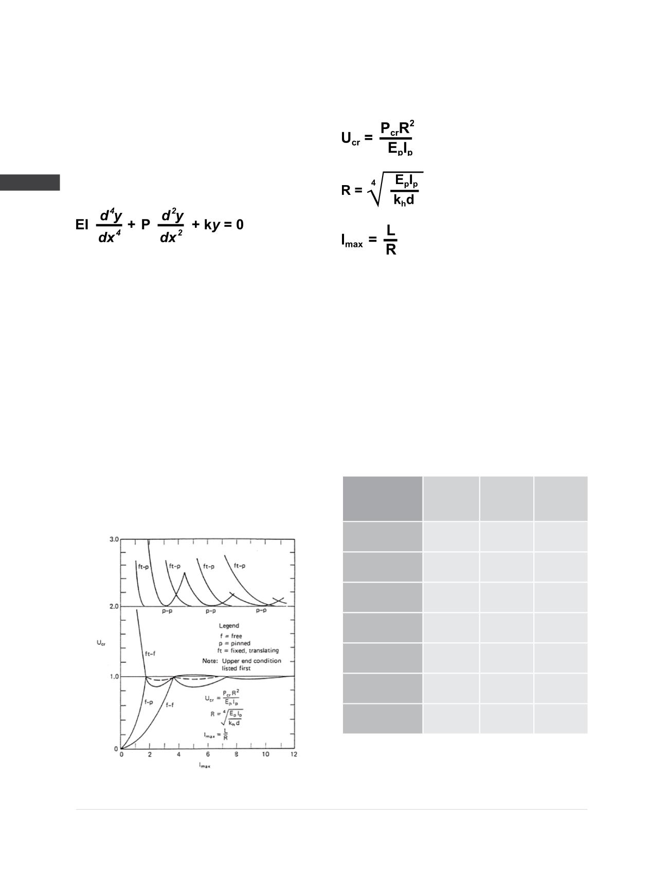
          The differential equation was solved for various
        
        
          boundary conditions using non-dimensional
        
        
          variables. The boundary conditions are free (f),
        
        
          pinned (p) and fixed-translating (ft). For initial
        
        
          conditions where the pile is fully-embedded,
        
        
          initially straight and the axial load is assumed
        
        
          constant (no skin friction), the dimensionless
        
        
          solutions are shown in
        
        
          Figure 2D.1
        
        
          . For further
        
        
          discussion of the derivation of these solutions
        
        
          the reader is advised to see the paper by
        
        
          Davisson (1963).
        
        
          The dimensionless variables are the critical axial
        
        
          load coefficient (U
        
        
          cr
        
        
          ) and the maximum value of
        
        
          the depth coefficient ( I
        
        
          max
        
        
          ) and are defined as:
        
        
          Where,


            P


            cr


          = Critical Axial Load


            R


          = Relative Stiffness Factor


            E


            p


            I


            p


          = Flexural Stiffness of the Pile


            k


            h


          = Horizontal Subgrade Modulus


            d


          = Pile Diameter


            L


          = Shaft Length over which k
        
        
          h
        
        
          is constant
        
        
          Typical values of k
        
        
          h
        
        
          for design purposes are
        
        
          shown in
        
        
          Figure 2D.2
        
        
          .


            Soil Type-


            Consistency


          Cohesion
        
        
          (psf)
        
        
          SPT
        
        
          N-value
        
        
          (bpf)
        
        
          Design kh
        
        
          (pci)
        
        
          Clay-Very Soft
        
        
          <250
        
        
          0-1
        
        
          <30
        
        
          Clay-Soft
        
        
          250-500
        
        
          2-4
        
        
          30
        
        
          Clay-Medium Stiff
        
        
          500-1000
        
        
          5-8
        
        
          100
        
        
          Sand-Very Loose
        
        
          (above GWT)
        
        
          NA
        
        
          0-4
        
        
          <25
        
        
          Sand-Very Loose
        
        
          (below GWT)
        
        
          NA
        
        
          0-4
        
        
          <20
        
        
          Sand-Loose
        
        
          (above GWT)
        
        
          NA
        
        
          5-10
        
        
          25
        
        
          Sand-Loose
        
        
          (below GWT)
        
        
          NA
        
        
          5-10
        
        
          20
        
        
          Figure 2D.2
        
        
          Typical design values for horizontal subgrade modulus
        
        
          (Reese, Wang et al. 2004b)
        
        
          Figure 2D.1
        
        
          Buckling load (load coefficient) vs. length
        
        
          (depth coefficient) for k
        
        
          h
        
        
          = constant (Davisson 1963)